I have been thinking about re-engineering the network for a while for a number of reasons, so this failure provided some impetus to get on with it. The new plan is to use a wifi bridge instead of the (RF prone) Ethernet cable. There are several plug and play bridges out there aimed at gamers, but these do not support multiple devices (i.e .include a router) at the end of the bridge. I decided to “roll my own” bridge using a Linksys WRT-54G TM re-flashed with DD-WRT.
|
MB7UBP has been off air for a while because my internet connection failed at home. I spent a short while tracing the problem and it seems that cable connecting the modem/router to the phone had become intermittent so moving the router closer to the phone point got me back on ADSL. However, it also moved the router away from my Ethernet link into my loft shack. Good for surfing, bad for radio. I have been thinking about re-engineering the network for a while for a number of reasons, so this failure provided some impetus to get on with it. The new plan is to use a wifi bridge instead of the (RF prone) Ethernet cable. There are several plug and play bridges out there aimed at gamers, but these do not support multiple devices (i.e .include a router) at the end of the bridge. I decided to “roll my own” bridge using a Linksys WRT-54G TM re-flashed with DD-WRT. DD-WRT has a really nice GUI and I have tried it before with various bits of embedded APRS software, but have never had much luck. It seems that the GUI uses so much RAM that the APRS software wouldn’t run. My experience this time was very different, the flashing was seamless, the set up as a bridge went exactly as per the wiki instructions and within 30 minutes I could turn off the wireless in my laptop and access the web via the bridge instead. All I have to do now is install the bridge in my loft shack I should be back in business!
0 Comments
I have posted before about rebuilding a ham radios station at the Gilwell Park (GP) Scout Activity centre. The only remaining part of the previous station is a damaged 3 element triband yagi on the 30m commercial tower. This hasn’t been used for two or three years and with the help of employees at Gilwell I am working towards getting the antenna changed by the tower owner. One problem came to the fore though. If the rotator needed changing as well as the yagi then the riggers would have a much bigger job to do. My task for the weekend was to work out how to reattach the cable dangling down the tower to the rotator control box and see if the antenna would turn. The control box had a bit of paper on the underside allegedly showing the connections to the main cable run, so on Saturday I popped over to GP and wired the whole thing up from outside the tower compound. The antenna turned but the indicator needle didn’t move at all. I suspected that pot in the rotator head had been damaged, but took the rotator controller home to make sure it was working properly. Whilst the control box was in bits I discovered a flat spot on the positioning pot in the rotator control box, but luckily I had a similar pot in my junk box so was able to swap it out. I had hoped this was the cause of the non moving needle and it was good to fix but certainly wasn't the core problem! I went back to GP on Sunday morning to test my handiwork but as per Saturday the antenna was still moving but the indicator needle was remained static. Time for some trouble shooting. Foolishly, I had used the diagram taped to the base of the control box showing the pin out of the control box, the colours of an intermediate jumper cable and how these both linked to the colours of the cables on the tower to the rotator motor and when things weren't working I realised I shouldn't have been so trusting. I decided that I had to work out role of each cable from scratch. This was made easier as the motor cables were clearly working and only 5 wires were required overall. That said, there were eight wires in the cable to the rotator head! On a couple of control box outputs the thin cables in the multi way jumper cable were being run in parallel to increase the current handling capability, but when I traced these through to the control box it became evident that several poles were being cross wired by the jumper. I thought I had found the problem but when I paired wires up correctly this didn't sort things out. So where now? Out came the DVM and I started to identify the role of the cables running down the tower. Once I had eliminated the motor power cables it was quite easy to discover which were the positioning pot in the rotator head. It was a great relief when I saw the resistance changing in this pair as I turned the antenna - the pot in the head was OK, meaning the problem was at ground level and therefore fixable. Phew. A quick comparison with the erroneous wiring diagram suggested that the original installer had actually wired the jumper cable to the main run like for like i.e. red to red, white to white etc, except of one pair where there had to be a mismatch. As I had already identified the motor pair and two of the control leads I knew that the all the remaining wires on the tower were either unused or the remaining "lost" connection. So, I wired them all in parallel and hey ho the rotator indicator started to turn with the antenna. It was a simple process of elimination to find out which of my parallel set was the real deal. So overall we have a result as shown in the video below. The antenna turns and the control box follows. I took a look at the main co-ax run to the antenna and the copper is bright - as new. This means we probably don't have to change that run unless I can find enough heliax. More good news! I will try to get back to GP soon with my soldering iron and VNA. If I put a PL259 on the remaining co-ax and sweep the antenna we will have an idea of performance. It may be that a 2.5 element yagi is usable and I think that this will be a bonus for JOTA in a few weeks time. I have been having some problems with my virgin media broadband connection over the last few days and it looks like the whole thing has finally fallen over completely. This means that MB7UBP is not gating to the internet until I can fix this!
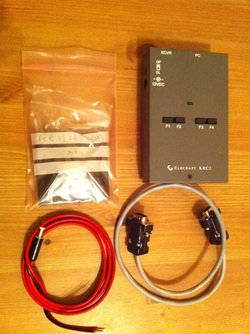
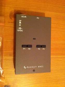
Hopefully it will be back on soon New toy alert! I have recently picked up an elecraft band decoder to use with my remote station. Elecraft got the kit over to me quickly and it is now assembled and ready to go. This bit of kit means that I can use the TS-480 to switch antennas at my eventual remote QTH. Icom and Yaesu radios are better at handling the band outputs than Kenwoods so the options for the 480 are quite limited but the guys on the TS-480 yahoo group say this one works a treat. I'll give it a go and see....
One interesting thing to come out of the discussion with M0RXW was his work with the omnima embedded controller for APRS. I have blogged before about using APRS4R running on an Asus router flashed with Openwrt here at MB7UBP to reduce the cost and environmental impact of the Igate and this has been running for about 2 years now. Whilst APRS4R works many folks, including me, find it a bit clunky to use. Furthermore the Asus routers are now out of production so the aprs4r development team are looking at other hardware platforms.
In the meantime Reuben, M0RXW, has got Openwrt and APRX running on the Omnima (which with box and programming cable costs about £50 or $75). The flashing process looks a bit more involved and there is no GUI for settings, but these are both problems for me with APRS4R so I am not worried about that. How long will I be able to hold out before I splash the cash to play with one? I suspect it won’t be long….. I have been on holiday for a week, so had to turn of the MB7UBP APRS I-gate to meet the shut down terms of its licence. M3SXA provides such good coverage of North London that I am not sure it was missed too much.
I used aprs.fi to look at my track after driving home (up the M20 from the Channel Tunnel and round the M25). I was surprised to see that there were some serious problems with the paths. This was backed up when a Kent I-gate owner, M0RXW enquired on the aprsig email list to solve the problem. |he group came up with an interesting solution – it seems that Alan, G3RJI’s new bi-directional I-gate, MB7UUE, is translating local internet packets to RF. I have no problem with this (*if* it is limited to very local packets) but, Alan has a great location and a high gain antenna giving him a large RF footprint and therefore high channel occupancy. This meant that timing of packets was being disrupted as the I-gate had to wait for a free slot on the air to TX a packet queued from the internet. As we have reasonable I-gate density around the perimeter of London the overall effect was to cause my position to jump around on the map. For example Time 1; M0BPQ-9 heard by M0RXW and gated to the internet at position X. Time 1: The channel at MB7UUE is busy so the position X received via the internet packet is stored until the freq is clear Time 2: M0BPQ-9 Heard by M0RXW and at position Y and gated to the internet Time 2: Channel clears at MB7UUE and the stored packets (including M0BPQ-9’s the out of date position X) are sent to RF Time 3: The MB7UUE packets are gated back to the internet by M0RXW. The overall effect on the internet map is the M0BPQ-9 travels from X to Y and then back again! What is there to learn form this? The main issue is to set your “ignore dupes received with n seconds” setting at the correct level if you are gating Internet to RF. Perhaps this needs to be longer for Internet sourced spots than it is for ones generated on RF? Secondly, perhaps I beacon too frequently when mobile? I will revisit my smart beacon settings to look at this. This is certainly not a criticism of Alan and his efforts to get more activity back onto RF (which I applaud), but an interesting example of the pitfalls faced by this system. I am happy to report that once Alan realised what was going on the resolved the problem quickly, so well done that man. |
AuthorA few notes on recent radio activity by Steve, M0BPQ. Archives
December 2020
Categories
All
|


 RSS Feed
