|
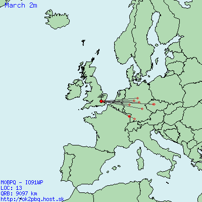
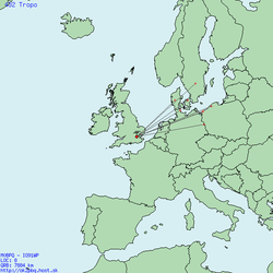
After watching the cluster on and off at work, I realized that the tropo had extended into a second day, but moving more to the South. After doing my domestic jobs at home I got back on the bands, this time looking at 2m. There were plenty of DLs around at 600Km and I spent a bit of time on the key, yielding two OKs both in a new square (#183). My 2m QSOs are mapped below. I also spent some time on 70cm, but didn’t hear much. I CQ’d for about 20 minutes but only worked DB6NT in JO50 with his typical rock crunching signal.
0 Comments
There has been some high pressure over the UK for the last few days and I suspected that this evening's 432 UKAC would be blessed with some good conditions. I wasn't wrong and managed to work several OZs and one SM. Pretty good going as my amp isn't working right now so I had 50W and mmy 18 element yagi. GU6EFB and MW6OXO were both active from squares that would be new for me on 70cm, but nothing was heard from either of them - they are my worst directions!
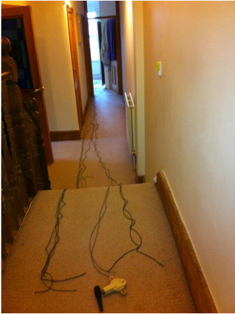
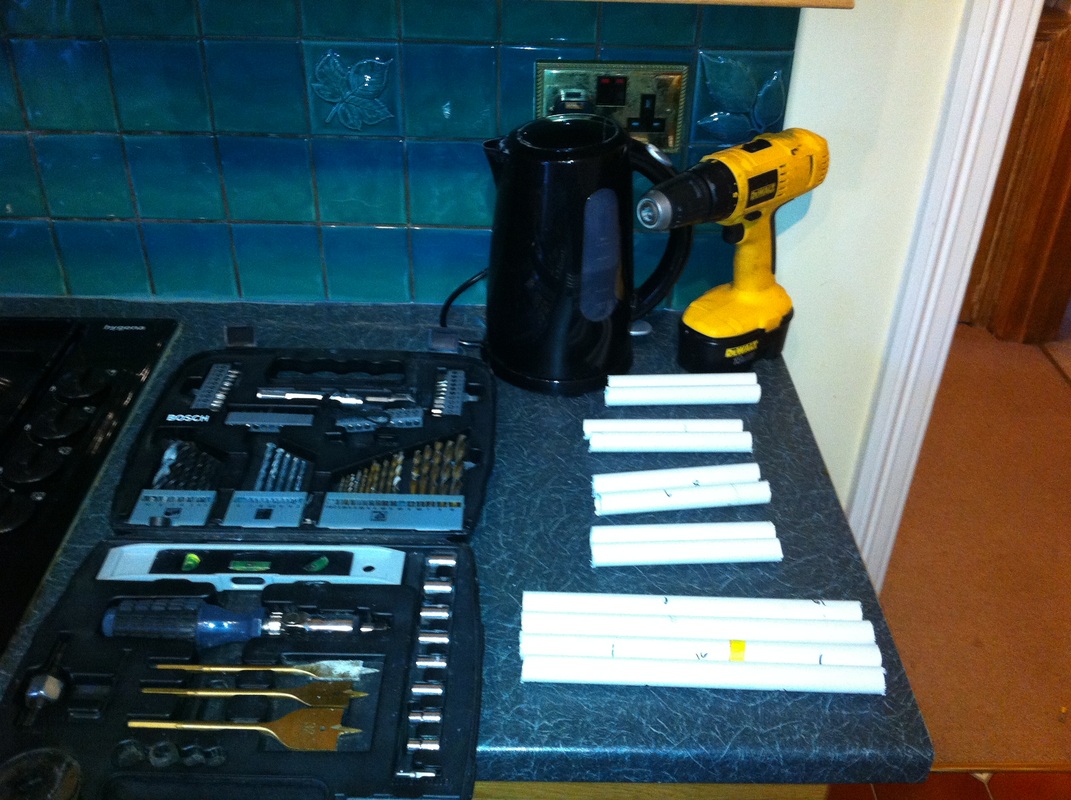
I did work the following stations though 13/03/2012 21:05 SK7MW JO65MJ 59 10 559 140 70 cm. SSB 963Km 13/03/2012 21:01 OZ9KY JO45VX 59 9 57 144 70 cm. SSB 808Km 13/03/2012 20:58 OZ9PZ JO46LC 53 8 53 64 70 cm. SSB 773Km 13/03/2012 20:45 OZ1DLD/P JO45SK 55 1 56 88 70 cm. SSB 764Km 13/03/2012 22:04 F8BRK IN99VF 55 17 57 102 70 cm. SSB 269Km were my best QSOs... Let's hope there is more to come I have tried a number of multiband wire antennas at GB2GP over the last year and have never been really happy with the results. The current antenna is a 1/3 2/3 split OCF dipole, which seems to work but still causes me a few problems. The main issue is that there is huge BCB breakthrough from Brookmans Park which is in LOS, so I am using a high pass filter at the transceiver to reduce this to a reasonable level. The filter is designed for 50 ohm impedance and the OCF is no where near that on all bands and even though the radio ATU can tune out any mismatch we toasted one of the filter torroids during JOTA due to the mismatch. The answer seems to be to use a resonant antenna for each band of interest. One of my neighbors, G0RPM, has had good results with a parallel dipole made by Alpha Delta. I called the UK importer Martin Lynch to enquire about these and was told by an unhelpful person they were out of stock and didn’t know when they would get any more in. As a result I have decided to stop being lazy and build one! The plan is to have an antenna for the 80-10m contest bands. This means four dipoles, 80m, 40m (which also works on 15m), 20m and 10m which I measured out in my hall from wire I had knocking about in my store. The next job was to build some spacers for the elements. A search on google suggests the spacing should be wide as possible to make tuning easier. I have a miniVNA which should simplify tuning so I decided to use only 75mm between wires. I picked up a length of PVC pipe from my local hardware shop cut it into pieces then 3mm drilled holes in my workshop (aka the kitchen). Feeding the wires through the holes was a simple job, but securing the spacers was more difficult. I tried hot melt glue, which was partially successful, but ended up using cable ties to produce my ladder effect. I had a spare commercial 1:1 balun which I put at the feed point and the antenna is ready to go in the air. Hopefully, installation will be an easy job, but I hope that I don‘t get too cold trying to tune the thing as the temperature here is not predicted to rise above freezing for a few days.
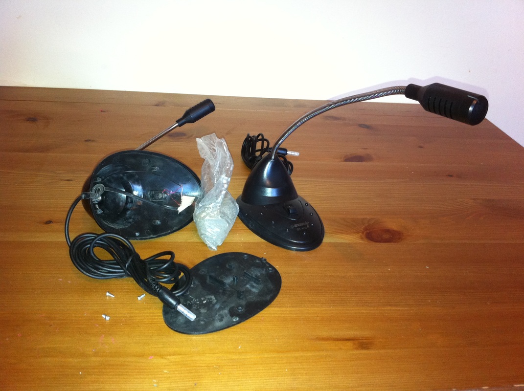
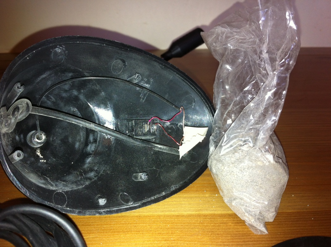
I usually use either a fist microphone or a headset when on the air, but my recent experiences at GB2GP have shown me that a desk microphone is useful when operating a special event station as it is easier for visitors to use on the air. GB2GP has two radios that don’t have microphones at the moment so I looked into building a couple of electret gooseneck desk mics from the ARRL handbook. Once I had costed up some parts that weren’t in my junk box this project felt too expensive until I saw PC desk mics on ebay for only £2 each. At that price I bought a couple and they arrived this morning. The external quality looked just fine - so far so good Like any good radio amateur, the first thing I did was take one apart to see how I could add a PTT. As expected the quality inside was only worth £2, but the thing that really surprised me was the bag of grit that had been inserted to add weight to the base! I guess it works, so why not stick with it, but I will be sealing the bag as I spilt half the contents on the floor when I tried to take it out of the microphone!
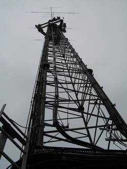
Next job is to change the flex to some 4 core and add an 8 pin microphone so they can be used with the TS-711 and TS-690S at GB2GP which shouldn’t take long. Here are a few old photos of the team installing the radio cabinet at GB2GP. FIrst of all te antennas on the mast Then the LDF5-50 run entering the LID building 30m of LDF 5-50 (for each of three antennas) runs inside the LID store room from the entry point to the celing over the radio cabinet. We installed cable tray to hold the weight of the run Finally the radio cabinet after fitting with Frank, M0AEU testing things out.
At a loss I haven’t blogged for a while – mainly because I have been too busy building stuff to write anything down. The main focus of my activity has been rebuilding kit to install at Gilwell Park, the Scouts Association’s HQ which holds the special call sign GB2GP. I will write about antennas another day, but I have been rather stumped by some recent measurements I have made on co-ax runs. The main coax runs at GB2GP will be Andrew Heliax LDF5-50 which is great news. 5-50 is a rigid cable so you have to use a loop of flexible cable around the rotator and other joints. As a result I bought some Ecoflex 10 from Terry at Diode Communications to do that job. It isn’t cheap, but has a good price:loss ratio! Terry did a great job in rushing the cable to me in bad weather at his end and I made up three lengths to go from the antenna feed point, down the boom (where required), round the rotator and then to the main 5-50 run. These lengths were 13m, 11m and 2m. The antennas are being fitted on a commercial tower by professional riggers so I wanted to make sure the cable assemblies were perfect as there is no second chance to fix mistakes. Using mini db calculator I estimated the losses on the highest frequency that it would be used on and compared them to the losses measured using both my mini VNA and calculated from power read using a Bird 43 wattmeter. The table below shows the losses for each bit of cable (db) and one major issue:
0.86db loss from a 3m length of cable! Shocking! This was the only cable that used a PL259,so I immediately suspected this to be the problem. I called Henry Westlake and ordered some pressure fit PL259s to ensure that the braid was properly installed, but this made no difference at all. I then wondered if the co-ax itself was not to spec and tested all of the runs on 432MHz as this could highlight any problems:
I am prepared to accept 0.2db variations from spec I had to use some inter series adapters and I am not using calibrated measurement gear, but it looks like I have a problem with that short run. If the PL259 is good, then the N-type at the other end must be the problem! What else can it be? I am at a loss…..
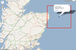
Some more tropo last night, so I spent time on 432 again looking for new stuff, but there wasn’t much around that I hadn’t worked before. I did manage a few OZs and DLs, but didn’t want to make too much noise with my little boy in bed. I had been hanging out on the ON4KST message system earlier in the day and during a chat with Martin GM6VXB he kindly agreed that we could try a sked if conditions looked promising. Around 9.30pm I stuck the antenna to the north and found the GB3ANG beacon at 559 – the first time I have heard it on 432. Back on KST Martin was good to his word and we had a quick QSO on 70cm followed by a more difficult one on 2m. A GM shouldn’t be a big deal, but Martin is in IO97aq and as the picture below shows, there isn’t much land in IO97 for a station to sit in! So, Martin, thanks a lot for looking for me – IO97 was new on two bands. More to come in the 432 UKAC contest tonight?
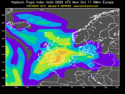
The weather here has been fine and dry over the weekend suggesting that we were under a high pressure weather system. High pressure can mean tropo openings on the VHF bands and a quick look at the Hepburn forecast on Friday suggested that there could be some fun ahead. I realised that the radio station was untested since I changed from PLT to a wifi bridge between the operating position and radio shack, so I spent an hour on Saturday making sure everything worked and also reinstalled the amplifiers following VHF NFD (which was only 3 months ago!). Luckily for me most of the system worked first time and I only had to spend a few minutes with the soldering iron. I didn’t hear much activity on Saturday, but on Sunday morning 144MHz started to open between Northern G/GM and Northern Europe (SM/SP/DL) and by dusk I too had propagation. There wasn’t much new for me on 2m, so I concentrated on 432MHz, working 8 stations in SM, OZ, DL and SP. ODX was SP1NQN at 1186Km, with four other contacts over 1000Km. I did briefly hear LY2WR at 1664Km, but he wasn’t strong enough with me for a QSO. It looks like there is a day or two of high pressure left so let’s hope for some more!
MB7UBP has been off air for a while because my internet connection failed at home. I spent a short while tracing the problem and it seems that cable connecting the modem/router to the phone had become intermittent so moving the router closer to the phone point got me back on ADSL. However, it also moved the router away from my Ethernet link into my loft shack. Good for surfing, bad for radio. I have been thinking about re-engineering the network for a while for a number of reasons, so this failure provided some impetus to get on with it. The new plan is to use a wifi bridge instead of the (RF prone) Ethernet cable. There are several plug and play bridges out there aimed at gamers, but these do not support multiple devices (i.e .include a router) at the end of the bridge. I decided to “roll my own” bridge using a Linksys WRT-54G TM re-flashed with DD-WRT. DD-WRT has a really nice GUI and I have tried it before with various bits of embedded APRS software, but have never had much luck. It seems that the GUI uses so much RAM that the APRS software wouldn’t run. My experience this time was very different, the flashing was seamless, the set up as a bridge went exactly as per the wiki instructions and within 30 minutes I could turn off the wireless in my laptop and access the web via the bridge instead. All I have to do now is install the bridge in my loft shack I should be back in business!
I have posted before about rebuilding a ham radios station at the Gilwell Park (GP) Scout Activity centre. The only remaining part of the previous station is a damaged 3 element triband yagi on the 30m commercial tower. This hasn’t been used for two or three years and with the help of employees at Gilwell I am working towards getting the antenna changed by the tower owner. One problem came to the fore though. If the rotator needed changing as well as the yagi then the riggers would have a much bigger job to do. My task for the weekend was to work out how to reattach the cable dangling down the tower to the rotator control box and see if the antenna would turn. The control box had a bit of paper on the underside allegedly showing the connections to the main cable run, so on Saturday I popped over to GP and wired the whole thing up from outside the tower compound. The antenna turned but the indicator needle didn’t move at all. I suspected that pot in the rotator head had been damaged, but took the rotator controller home to make sure it was working properly. Whilst the control box was in bits I discovered a flat spot on the positioning pot in the rotator control box, but luckily I had a similar pot in my junk box so was able to swap it out. I had hoped this was the cause of the non moving needle and it was good to fix but certainly wasn't the core problem! I went back to GP on Sunday morning to test my handiwork but as per Saturday the antenna was still moving but the indicator needle was remained static. Time for some trouble shooting. Foolishly, I had used the diagram taped to the base of the control box showing the pin out of the control box, the colours of an intermediate jumper cable and how these both linked to the colours of the cables on the tower to the rotator motor and when things weren't working I realised I shouldn't have been so trusting. I decided that I had to work out role of each cable from scratch. This was made easier as the motor cables were clearly working and only 5 wires were required overall. That said, there were eight wires in the cable to the rotator head! On a couple of control box outputs the thin cables in the multi way jumper cable were being run in parallel to increase the current handling capability, but when I traced these through to the control box it became evident that several poles were being cross wired by the jumper. I thought I had found the problem but when I paired wires up correctly this didn't sort things out. So where now? Out came the DVM and I started to identify the role of the cables running down the tower. Once I had eliminated the motor power cables it was quite easy to discover which were the positioning pot in the rotator head. It was a great relief when I saw the resistance changing in this pair as I turned the antenna - the pot in the head was OK, meaning the problem was at ground level and therefore fixable. Phew. A quick comparison with the erroneous wiring diagram suggested that the original installer had actually wired the jumper cable to the main run like for like i.e. red to red, white to white etc, except of one pair where there had to be a mismatch. As I had already identified the motor pair and two of the control leads I knew that the all the remaining wires on the tower were either unused or the remaining "lost" connection. So, I wired them all in parallel and hey ho the rotator indicator started to turn with the antenna. It was a simple process of elimination to find out which of my parallel set was the real deal. So overall we have a result as shown in the video below. The antenna turns and the control box follows. I took a look at the main co-ax run to the antenna and the copper is bright - as new. This means we probably don't have to change that run unless I can find enough heliax. More good news! I will try to get back to GP soon with my soldering iron and VNA. If I put a PL259 on the remaining co-ax and sweep the antenna we will have an idea of performance. It may be that a 2.5 element yagi is usable and I think that this will be a bonus for JOTA in a few weeks time. |
AuthorA few notes on recent radio activity by Steve, M0BPQ. Archives
December 2020
Categories
All
|
||||||||||||||||||||||||||||||||||||
 RSS Feed
